
10Micron AZ-HPS Mounts offer a line of premium altazimuth mounts based on the company’s popular GM-HPS line of super-accurate, absolute encoder German equatorial mounts.
The 10Micron AZ-HPS series of mounts use the same absolute encoder technology as the GM-HPS mounts with instrument capacities from 55 to 330 pounds. The capability to mount single, dual, triple and quad scopes is available in the AZ2000HPS, AZ3000HPS and AZ4000HPS models.
While not suitable for long-exposure imaging without the use of a rotator, the 10Micron AZ-HPS mounts are well suited for visual astronomy, planetary and short-exposure astrophotography, supernova surveys, asteroid and comet surveys, video astronomy, satellite tracking, photometric and astrometric measurements, and other scientific uses. Their extremely precise targeting and tracking (even in an alt/az configuration) are perfect for survey work.
AZ1000 HPS
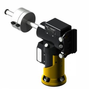 The AZ1000 HPS is a versatile, light and transportable mount that offers precision absolute axis-encoders; a control box with onboard-intelligence (Linux-processor); V. 2 – HPS version firmware, standalone system (no PC required); professional hand control unit with graphic display and temperature control; Losmandy 3″/Vixen GP dovetail plate; integrated WiFi; cables; counterweight bar and a strong transport carton-box with shaped foam.
Specifications include:
Weight: 19.5 Kg (43 lbs)
Instrument payload capacity: 25 Kg (55) lbs
Counterweight shaft: 30mm diameter, stainless steel
Axes: 30 mm diameter, alloy steel
Bearings: Pre-loaded tapered roller bearing
Worm wheels: 250 teeth, 125 mm diameter, B14 bronze
Worm screw: 20mm, tempered alloy steel, grinded and lapped
Transmission system: Backlash-free system with timing belt and automatic backlash recovery
Motors : 2 axes servo brushless
Power supply: 24 V DC
Power consumption: ~ 0,5 A while tracking ~ 3 A at maximum speed ~ 4 A peak
Go-to speed: Adjustable from 2°/s to 15°/s
Pointing accuracy: < 20” with internal multiple-stars software mapping
Average tracking accuracy: < +/− 1″ typical for 15 minutes (< 0.7″ RMS) with internal multiple-stars software mapping and compensation of flexure and polar alignment errors
Security stops: +/− 150° in AZ (software) +/− 155° in AZ (mechanical); +/− 95° in Alt (software) +/− 100° in Alt (mechanical)
Operational temperature range (standard): – 15° C to + 35° C (+ 05° F to + 95° F)
Storage temperature range: – 40° C to + 50° C (- 40° F to +122° F)
Communication ports: RS–232 port; GPS port; autoguide ST-4 protocol port; Ethernet port
AZ2000 HPS
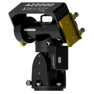 The standard version allows the assembly of the optics to only one side of the mount and is supplied with a short counterweight bar. An option is available for a dual telescope configuration.
Interestingly, the AZ2000 was produced for a customer in a one-off special “Antarctica” version, which was able to work at the extreme low temperature of -84°C (-119F). Special mechanical and electronic considerations were necessary in order to design and produce this peculiar mount: from the correct choice of material and sizes to the use of special and very expensive lubricants, wiring and connectors. A special housing was also designed to protect against temperature and ice crystal formation and which needed different levels of seals depending on the effective operational temperature. 10Micron can produce the AZ2000 mount for low temperature operations upon request.
The mount offers precision absolute axis-encoders; a control box with onboard-intelligence (Linux-processor); V. 2 – HPS version firmware, standalone system (no PC required); professional hand control unit with graphic display and temperature control; Losmandy 3″/Vixen GP dovetail plate; integrated WiFi; cables; counterweight bar and a strong transport carton-box with shaped foam.
Specifications include:
Weight: 30kg (66lbs)
Instrument payload capacity: 50 kg (110 lbs)
Latitude Range: 23° – 70°
Azimuth Fine Adjustment Range: +/- 10°
Counterweight Shaft: 40mm diameter, stainless steel, weight 9 lbs (4 kg)
Axes: 50mm diameter, alloy steel
Bearings: Pre-loaded tapered roller bearings
Worm wheels: 215 teeth, 172mm diameter, B14 bronze
Worms: Diameter 24mm, tempered allow steel, ground and lapped
Transmission system: Backlash-free system with timing belt and automatic backlash recovery
Motors: AC servo brushless
Power supply: 24 VDC
Power consumption: Approx. 0.7A while tracking, Approx. 3A at maximum speed, Approx. 5A peak
Goto speed: Adjustable from 2°/sec. to 20°/sec.
Pointing Accuracy: < 20″ with internal multi-star software mapping
Average Tracking Accuracy: Approx. 1″ typical for 15 minutes; Approx. 0.6″ RMS with internal 25-star software mapping and compensation of flexure and polar alignment errors
Safety stop: +/- 150° past meridian in RA (software); +/- 95° past meridian in RA (mechanical)
Communications Ports: RS-232 port, GPS port, autoguide ST-4 protocol port, Ethernet port
AZ 3000 HPS
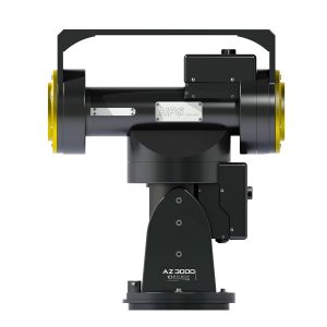 The new AZ3000 HPS also offers the option for option for a dual telescope configuration and can be provided as a special order for low temperature operations.
The mount offers precision absolute axis-encoders; a control box with onboard-intelligence (Linux-processor); V. 2 – HPS version firmware, standalone system (no PC required); professional hand control unit with graphic display and temperature control; Losmandy 3″/Vixen GP dovetail plate; integrated WiFi; cables; counterweight bar and a strong transport carton-box with shaped foam.
Specifications include:
Weight: 65 kg (143 lbs)
Instrument payload capacity: 100 kg (220 lbs)
Azimuth fine adjustment range (for initial orientation): +/− 10°
Counterweight shaft: 50 mm diameter, stainless steel
Axes: 80/50 mm diameter, alloy steel
Bearings: Pre-loaded tapered roller bearing
Worm wheels: 315 teeth, 247 mm diameter, B14 bronze (AZ); 255 teeth, 192 mm diameter, B14 bronze (Dec)
Worm screw: 32mm and 24mm, tempered alloy steel, grinded and lapped
Transmission system: Backlash-free system with timing belt and automatic backlash recov
Motors: 2 axes servo brushless
Power supply: 24 V DC
Power consumption: ~ 1 A while tracking ~ 3 A at maximum speed ~ 5 A peak
Go-to speed: Adjustable from 2°/s to 12°/s; Special version 48V: from 2°/sec to 20°/sec
Pointing accuracy: < 20” with internal multiple-stars software mapping
Average tracking accuracy: < +/− 1″ typical for 15 minutes (< 0.7″ RMS) with internal multiple-stars software mapping and compensation of flexure and polar alignment errors
Security stops: +/− 150° in AZ (software) +/− 155° in AZ (mechanical); +/− 95° in Alt (software) +/− 100° in Alt (mechanical)
Operational temperature range (standard): – 15° C to + 35° C (+ 05° F to + 95° F)
Storage temperature range: – 40° C to + 50° C (- 40° F to +122° F)
Special operational temperature range: Optional, for very low temperature operations
Communication ports: RS–232 port; GPS port; autoguide ST-4 protocol port; Ethernet port
AZ4000 HPS
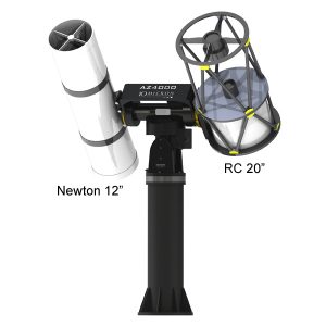 The AZ4000 is capable of carrying a single instrument of up to 150kg (330lbs). The mount is available in a double telescope version which allows the use of 2 to 4 optics in a side by side setup with a capacity of 250kg (550lbs), optimizing the load of the mount and taking advantage of the altazimuth configuration. The mount can be provided as a special order for low temperature operations.
The new AZ3000 HPS also offers the option for option for a dual telescope configuration and
The mount offers precision absolute axis-encoders; a control box with onboard-intelligence (Linux-processor); V. 2 – HPS version firmware, standalone system (no PC required); professional hand control unit with graphic display and temperature control; Losmandy 3″/Vixen GP dovetail plate; integrated WiFi; cables; counterweight bar and a strong transport carton-box with shaped foam.
The AZ4000 HPS Mount is available in a special 48 V version in order to reach a faster slewing speed of 12°/sec.
Specifications include:
Weight: 125 kg (276 lbs)
Instrument payload capacity: 150 kg (330 lbs) for standard single telescope configuration; 150 + 100 kg (330 +220 lbs) for optional dual telescope configuration
Azimuth fine adjustment range (for initial orientation): +/− 10°
Counterweight shaft: 60 mm diameter, stainless steel, weight 13 kg – 29 lbs
Axes: Azimuth: 85mm diameter; Alt 80mm diameter, alloy steel
Bearings: Pre-loaded tapered roller bearing
Worm wheels: Azimuth. 430 teeth, 330 mm diameter, B14 bronze; Alt. 315 teeth, 244 mm diameter, B14 bronze
Worm gears: Diameter 32mm, tempered alloy steel, grinded and lapped
Transmission system: Backlash-free system with timing belt and automatic backlash recovery
Motors : 2 axes servo brushless
Power supply: 24 V DC (48V DC as special option)
Power consumption: ~ 1,5 A at sidereal speed; ~ 4 A at maximum speed; ~ 5 A peak
Go-to speed: Adjustable from 2°/s to 8°/s (6°/s in R.A.); Special version 48V DC from 2°/s to 12°/s (10°/s in R.A).
Pointing accuracy: < 20” with internal multiple-stars software mapping
Average tracking accuracy: < +/− 1″ typical for 15 minutes (< 0.7″ RMS) with internal multiple-stars software mapping and compensation of flexure and polar alignment errors
Security stop: +/− 150° in AZ (software) +/− 155° in AZ (mechanical); +/− 95° in Alt (software) +/− 100° in Alt (mechanical)
Operational temperature range (standard): – 15° C to + 35° C; + 05° F to + 95° F
Storage temperature range: – 40° C to + 50° C; – 40° F to +122° F
Special operational temperature range: Optional, for very low temperature operations (until -35°C / -31°F)
An Overview of HPS Technology
HPS means “High Precision and Speed.” 10Micron has provided the following overview of the HPS technology.
The AZHPS mounts feature two high-precision absolute encoders mounted directly on each axis to ensure unprecedented pointing and tracking accuracy, and high-performance servo motors and drivers for high speed pointing.
In the vast majority of applications, including long exposure deep-sky imaging, the need for autoguiding is eliminated. The pointing accuracy allows you to be confident that, once the mount is properly setup, objects will be centered in the smallest field of view, even with a mobile setup. Furthermore, the internal electronics allows the mount to do almost everything without the need for an external PC.
The encoder system
The absolute encoders provide high-accuracy, sub-arcsecond feedback to the motion of the mount. The absolute encoders render the axes “live” and free to react also to any external forces like wind and vibrations or accidental contact. This feedback is provided regardless of any zeroing or homing procedure.
This means that the electronics will always know the position of the mount. You may move the mount with the clutches unlocked and the electronics powered off, lock the clutches in any position and switch on the mount: the electronics will know where the telescope is looking. You may effectively use the mount as a Dobsonian telescope with manual pointing, retaining the full, sub- arcsecond accuracy of the encoders. This means ease of use when operating in the field, since the setup procedure is much faster.
With regard to the right ascension axis, virtually all the mechanical error from the reduction gearing is eliminated. Not only the “Periodic Error”, which comprises the periodic irregularities due to imperfection in the manufacturing and assembling of the worm, but also the non-periodic errors due to imperfections in the wormwheel, bearings, belts and so on.
With regard to the declination axis, it may seem that the encoder system is less important, since there is no sidereal tracking motion. The company points out that the declination axis is critical to sidereal tracking. If you want to compensate for refraction, telescope and mount flexure and so on, you will have to move the declination axis at very small speeds. While the right ascension axis works always at the same speed (plus or minus small corrections), the declination axis works always at near-zero speeds, with the occasional inversion of the direction of motion. This means that mechanical backlash, belt flexure and friction forces show in the declination axis.
The company says that the system eliminates the need to find ways to minimize the effect of these forces in traditional mounts such as having very small preload on the worm, with the risk of uncontrolled motion when the telescope is subjected to even small external forces, because of the disengaging of the worm from the wormwheel; painstakingly calibrating software backlash compensation procedures; manually adjusting the meshing of gears or introducing forcefully small alignment errors, to force autoguide corrections always in the same direction.
Tracking objects and mount modelling
The task of tracking astronomical objects can be decomposed into several sub-tasks including.
– Modelling the orientation of the mount with respect to Earth.
– Modelling the orientation of the telescope with respect to the mount.
– Modelling the errors of the mechanical system with respect to an “ideal” one.
– Modelling the influence of the atmosphere on the path of light rays.
– Modelling the orientation of Earth.
– Modelling the motion of astronomical objects themselves.
In order to obtain the sub-arcsecond tracking accuracy of HPS mounts, 10Micron says that all of these factors must be taken into consideration.
Modelling the orientation of the mount with respect to Earth
An ideal equatorial mount has its right ascension axis pointed directly at the celestial poles. If there are errors with this, the mount will exhibit various pointing and tracking errors, in both axes, varying across the sky. So, with a typical mount that tracks objects by setting a constant velocity on its right ascension axis, it is of utmost importance to approach this ideal situation.
There are many methods for achieving this, from the universal Bigourdan method, to iterative methods exploiting the capabilities of computerized mounts, to the traditional polar scope. Many computerized mounts allow you to point to one, two or three stars, with less and less assumptions on the correctness of the initial alignment and compute the polar misalignment. This information is then used for pointing at objects.
The HPS mounts can do the same as with these methods, with the additional usage of this piece of information for correcting the tracking of objects. This means that tracking objects will always be correct, even if the mount is not aligned to the celestial pole. You may want to ensure a reasonably correct alignment to avoiding field rotation on long sequences of imaging. Various functions are provided by the 10micron firmware: even the number of turns you must apply to the adjustment handles for the azimuth and altitude is given.
So the HPS technology eliminates the polar scope to the advantage of mechanical stiffness of the mount, since the initial alignment can be done with the mount misaligned even by many degrees from the pole, and approximately centering two bright stars in the eyepiece (using even manual movements, like in a Dobsonian), then centering a third star with the adjustment handles.
All of this requires a reasonably accurate knowledge of time and your location on Earth. If you plan to reuse the alignment later (for example if you are in an observatory), you will have to keep the mount’s clock accurately synchronized and use very precise coordinates for your site. For this reason, beyond the usual data entries from the keypad or with an external PC, 10Micron mounts support reading all these data from an optional GPS module.
Modelling the orientation of the telescope with respect to the mount
Your telescope’s optical axis will not be perfectly perpendicular to the declination axis, and it will not be perfectly aligned with the zero angle of the absolute encoder. When you add the third star to the alignment procedure, these errors are automatically computed and corrected in the future.
Modelling the errors of the mechanical system with respect to an “ideal” one
Even with high-accuracy encoders mounted directly on the axes, there is still the issue of mechanical flexure. In a number of mounts the mechanical errors are not dealt with at a software level. While mechanical errors can minimized through careful designing and manufacturing. As the company points out, if you allow for an error of one arcsecond during the exposure of an image, a little calculation will show that this error can be introduced by a deformation of a leg of the typical tripod of just 5 thousandths of a millimeter. A deformation like this can be easily caused just by moving around the barycenter of a non-perfectly balanced telescope.
The HPS system accounts for the mechanical flexure of the mount and telescope. It does so by pointing to various locations in the sky, and comparing them against the encoder readout (i.e., the absolute angle set on the mount’s axes). With enough points, flexure can be modeled well enough to allow for high-precision pointing.
With 10Micron AZ-HPS mounts, the procedure can be as simple as adding stars to the ones you already used for the initial alignment. This can be automated in a very efficient way by using external tools that point to a predefined set of locations in the sky, take a picture, measure the exact coordinates by a process called “plate solving” and feed the coordinates back to the mount. You can use up to 100 alignment stars/points for this task, and everything can be done in a surprisingly little amount of time, thanks to the high pointing speed.
All of this works if mechanical errors are repeatable. This means that, while mechanical flexure can be usually modeled with excellent accuracy, this doesn’t apply to mechanical play or backlash. The on-axis encoders ensure that no backlash in the mount will get in your way while creating a pointing model, tracking or pointing objects, while you have the task of eliminating flopping mirrors, loose focuser tubes and so on.
Modelling the influence of the atmosphere on the path of light rays
Atmospheric refraction is the result of the earth’s atmosphere bending the rays of light from astronomical objects, depending on air density. With traditional mounts, often it is advised to point the right ascension axis to the refracted celestial pole, and set a special tracking speed that compensates for the apparent speed difference due to refraction (in right ascension only).
10micron mounts allow for setting of the barometric pressure and atmospheric temperature, and even changing offer the ability to incorporate changes in these during an observation session, in order to continuously correct their pointing and tracking to account for atmospheric changes. This can be done manually, with the keypad, or from an external PC.
Modelling the orientation of Earth
The earth rotates with respect to astronomical objects. By far, its main motion is the daily rotation. So, for being called an “equatorial mount”, often it is enough to provide a constant-rate rotation around the right ascension axis. This rate, usually, is given by a quartz clock, and so it should be reasonably accurate. However typical quartz oscillators used in electronics (and also in a typical PC) are not temperature compensated. At a fairly typical temperature of -5°C (23°F), which is not rare for astronomical observation, a typical quartz can have an error of tens of parts per million (ppm). Errors of 20 or 30 ppm are commonly observed, which would cause errors in right ascension accumulating at about 2.5 seconds per day, which means more than one arcsecond per hour. The loss of pointing precision in a 12-hour winter night would be of about 20 arcseconds, and much more if the mount is shut down and powered on days later.
This can be corrected by keeping the mount always synchronized to an external time source, like a standard PC with its clock synchronized to the NIST time servers, or with the optional GPS module. All 10Micron motor drivers feature a battery-backed clock with temperature compensation, which is able to keep time with an accuracy of 3.5 ppm from –40°C to +40°C (–40°F to +104°F).
A much slower, but nevertheless fundamental, movement is the precession of equinoxes. If you don’t model the precession, you are forced to use standard coordinates (for example, when doing alignment
Precession changes the direction of the Earth’s rotation axis, i.e. the celestial pole, and some systems do not account for precession in their databases. By default, 10Micron AZ-HPS mounts work in JNOW when communicating with the outside, i.e. the coordinates you read and set in the keypad are referred to the true equinox of the date of observation. But everything is accounted for in the firmware, even nutation and light aberration.
Another factor which can limit the accuracy of the mount over long periods is the change in Earth’s rotation rate. What we call the “UTC time” is only an approximation to the angle of rotation of Earth. The angle of rotation of Earth is measured by UT1, if we neglect the pole wandering and seasonal variations, (that amount to less than one arcsecond). UTC is based on atomic clocks, and sometimes a so-called “leap second” is inserted into it to maintain it within 0.9 seconds of UT1.
So, when you approximate UT1 with UTC, you may introduce a difference of up to 14 arcseconds into your pointing accuracy. This difference changes very slowly, so that the degradation of pointing models (simply due to terrain creeping and other “very slow” things) is always faster than this change, and you will not notice any problem in practice. But when the leap second is inserted, you have a sudden jump in coordinates. 10Micron has implemented a full accounting of UTC, UT1 and leap seconds since firmware revision 2.13.1.
Modelling the motion of astronomical objects themselves
Quite a number of astronomical objects exhibit a visible movement including planets, asteroids, comets, and artificial satellites of the Earth. The firmware of 10micron mounts can compute the motion of all these objects directly from their orbital parameters (except for planets, you will have to upload orbital parameters into the mount).
Why not autoguiding? It seems simpler…
For the user, autoguiding means additional work. When using an external guider scope, you can’t compensate all flexures between the two instruments, and you have additional, heavy equipment. When using a dedicated guider camera, it means additional cabling, software installation, setup and searching for suitable guide stars, looking for customized guiding software parameters, calibration. HPS mounts can be aligned to bright stars during twilight, then every second of darkness can be used for imaging. For those who prefer autoguiding capabilities, mounts provide a standard ST4 port, as well as all the usual settings and controls by remote software.
Pointing objects
10Micron AZ-HPS mounts feature a very rich database of objects, including the classical Messier and NGC/IC catalogues, as well as many catalogues of stars, including variables and doubles, and of deep-sky objects. Also, a catalogue of moon features is available and useful thanks to the high pointing accuracy.
The high speed of the mount is necessary, beyond speeding up the alignment procedures, for fast satellites catching (especially after a meridian crossing). Furthermore, it helps to reduce loss of time in research applications, increasing the amount of data that can be obtained in the often short observing nights.
Instrument setup
The 10Micron AZ-HPS mounts feature a variety of accessories for mounting various instruments. Even multiple instruments can be mounted on a single mount, in order to have the right imaging equipment always ready. Since the pointing and tracking model depends on the specific instrument (the flexure is different), the mount allows for different models, one for each instrument, that can be saved in the internal memory and reloaded when required.
Another useful feature, especially for heavier mounts, is the electronic balance function. With this function you may measure the unbalancing of the instrumentation and adjust accordingly. The high speed is very useful also in quickly accomplishing up this procedure.
Remote operation and connectivity
The HPS mounts offer a number of connecting options. While you may choose the traditional RS-232 connection to control the electronics from an external PC, you may prefer to dedicate it to directly controlling a computerized dome. The firmware will provide all the relevant computations, even for mounts that are mounted off-center and instruments mounted with offset.
The GPS port doubles as an additional RS-232 port, if you don’t use the GPS. The recommended way of connecting the mount to your PC is using the LAN connection, via TCP/IP, or the Wireless connection. The mount can connect to an existing WLAN, or it can be used as a hotspot to which your PC, tablet or smartphone can connect.
The LAN connection offer superior high-voltage tolerance with respect to the typical RS-232 connection; this is even better with the WLAN which is wireless. In case of remote observatories, which are subject to lightning, this may make the difference between healthy electronics and fried ones.
The mount supports up to ten simultaneous TCP/IP connections, so you can use different software and different devices at the same time. 10micron provides an ASCOM driver for Windows, but if you want to implement your own control system, they provide the command set that can be used both on the RS-232, LAN and WLAN connections. The command set is largely LX200 compatible and also includes many more functions and operating modes. In remote operation, there is the additional security provided by the absolute encoders – in no case you will lose your alignment, even in case of slipping clutches.
The HPS mounts are able to operate up to 30° beyond the meridian, in both directions (this means, with the counterweight bar up, and the telescope down). This allows at least an arc of 60° for tracking every object, corresponding to at least four hours of tracking for objects crossing the meridian (provided that the object doesn’t set or encounter another limit). This amount is configurable from 0° to 30° to obtain the maximum flexibility. The mount will warn you when it is reaching tracking limits and when at the limit, tracking will stop. You will have to point the object again to force a meridian flip.
 And to make it easier for you to get the most extensive telescope and amateur astronomy related news, articles and reviews that are only available in the magazine pages of Astronomy Technology Today, we are offering a 1 year subscription for only $6! Or, for an even better deal, we are offering 2 years for only $9. Click here to get these deals which only will be available for a very limited time. You can also check out a free sample issue here.