
Cyclope Seeing Monitor Review
What is “seeing” and why do we care?
In 2010, I built a remote observatory in the Texas Hill Country. The main telescope is an RC Optical Systems 16-inch carbon truss. The observatory is robotic and can be controlled over the internet, which has expanded my opportunity to image whenever the skies allow. I used to hope for clear moonless nights and would watch the clear-sky clock and weather forecasts. Some nights, although clear and bright, were dismal and disappointing – the images were fuzzy and stars were bloated. Although this occurred infrequently, I wondered why.
Before installing my telescope, I studied many articles about focal length, image scale and how to optimize those for efficient imaging, but now I was seeing those interactions for myself. My focal length is about 3620 mm, and my pixel size is 9-microns, yielding an image scale of approximately 0.50-arc seconds per pixel. I gained experience that some nights, although clear with no Moon, were no good for imaging.
I began consulting the clear-sky chart and jet-stream data for my location and discovered a correlation between the “seeing” predictions from those sources and what I was experiencing with my telescope. So, what is “seeing?”
Think about a penny at the bottom of a swimming pool. The penny is difficult to see clearly, because the water is refracting the image – the penny is wavy, shifts and moves, with short moments of clarity. Now look up into the night sky. The same thing is happening. The atmosphere is a turbulent mass of air that refracts the light from stars and deep-sky objects. This turbulence is primarily caused by temperature differences in the Earth’s atmosphere that create variations in the optical refractive index of the atmosphere.
The atmosphere is composed of cells of different temperatures that refract light differently. Although stars are point sources of light, viewing a star through our atmosphere will make it appear to jump around and even twinkle as the light is refracted through these different temperature cells. So, “seeing” describes how well you can discern astronomical objects through the Earth’s atmosphere as it refracts the light from those objects on a given night and location.
How do you measure “seeing?”
Although a star is a point source of light, the atmosphere will refract and blur the star making it appear like a disk with a real diameter. Your telescope does the same thing through refraction and yields the “Airy disk.” Measuring seeing means to ascertain the best possible angular diameter of that point source of light achieved by the specific telescope on a given night and location. Of course, when measuring angular diameters on the celestial sphere, we use measures of arc. Thus, when measuring the seeing, we use arc seconds to represent the angular size of the fuzzy blob of the star seen through the telescope. The best locations on Earth give a seeing disk diameter of 0.4 arc seconds. Average seeing conditions in North America can range from 1 arc second (or below) to 5 arc seconds
How does seeing affect viewing through telescopes of different focal lengths?
The ultimate resolution of a telescope is generally thought of as its diffraction-limited resolution and is inversely proportional to the diameter of the telescope. The more aperture you have, the greater the telescope’s theoretical resolution. If the telescope, however, has a resolution greater than the seeing in arc seconds, then some of that resolution is wasted. The seeing will limit the resolution. This is why large aperture telescopes don’t fare as well on nights of poor seeing – the larger aperture (and resolution) is wasted.
This was an important realization for me. If I could obtain an accurate measurement of the local seeing on a given night, I could make a more informed decision about whether to image that night. This was even more important to know if I intended to image remotely. I started to investigate what hardware/software systems were available to an amateur astronomer for measuring the seeing.
The Alcor Systems Cyclope Seeing Monitor
At the 2015 Advanced Imaging Conference (AIC) held in San Jose, California, I met Cyril Cavadore from Alcor Systems, which is based in France. Cyril, an engineer in Opto Electronics, obtained his PhD in CMOS image sensors and has been involved in astronomy instrumentation for more than 25 years. Alcor Systems’ products include all-sky cameras, direct drive mounts and seeing monitors, to name a few. As to software, they make the Prism astro-imaging/planetarium software package that can run all aspects of an observatory.
At AIC, Cyril was demonstrating Alcor Systems’ seeing monitor product, aptly named “Cyclope.” I was intrigued by the demonstration of the Cyclope system, because it is well built and employs a CMOS digital video camera system capable of very high frame rates, which improves accuracy in measuring the seeing and provides a real-time computation of the seeing.
Also, the system has weather monitoring and a heated front window for the camera. The Cyclope Seeing Monitor system can be ordered with either a USB or Ethernet interface. Each system is built to order, specifying the type of interface and length of cabling needed. Ultimately, I placed an order for an Ethernet version.
Theory/Principle of Operation
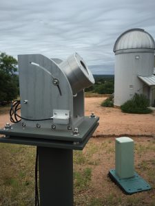
The video-camera housing is mounted in an altitude axis that can be adjusted depending on your latitude. The camera must be polar-aligned with the camera fixed on Polaris (Image 1). Polaris is moving around a circle with a radius of 0.75 degrees from true north. The Cyclope camera has a field of view of 3.6 x 2.5 degrees, and therefore, Polaris will remain within the camera’s field of view during a full 24-hour rotation of the Earth. This means, no tracking is necessary for the Cyclope system to continually monitor a star to determine the seeing.
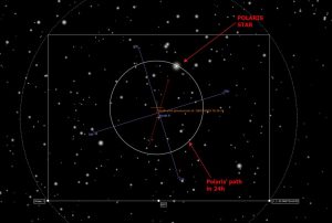
Also, Polaris is bright enough at 2nd-magnitude to allow its position to be measured at 50 to 60 frames per second (1/125-second exposures), even through a green filter (550 nm). Using Polaris for seeing measurements is effective from latitudes ranging from 90 degrees North down to 25 degrees North (Image 2).
The tip-tilt motion of Polaris is measured 50 to 60 times per second, and the Cyclope software computes the seeing at the altitude of Polaris and also computes a zenith seeing condition based on these measurements. Due to the high frequency of these measurements and the small pixel size of the video camera, Alcor Systems maintains that the Cyclope system is much more accurate than other seeing monitors, especially in conditions where the seeing is 1.5 arc seconds, or lower.
The benefits of the Cyclope Seeing Monitor system mentioned by Alcor Systems include (1) robust, all weather-use construction, which limits vibrations that can impair seeing measurements, (2) better measurement accuracy, because the camera utilizes more pixels with a smaller pixel size, (3) high frame rates that allow the system to accurately measure very low seeing (below 1.5 arc seconds), (4) Ethernet or USB interfaces, and (5) automatic heating of front camera window to prevent dew or frost.
Alcor Systems has undertaken studies to compare the accuracy of the Cyclope system to a differential image motion monitor (DIMM). A DIMM system employs a dual-aperture mask over a telescope’s aperture. Images are recorded and the variance of the coordinates for the two images is used to compute the seeing using a turbulence model. Based on Alcor Systems’ study, the Cyclope System achieves seeing measurements nearly identical to a DIMM system. More information about the study can be found at here.
Installation Hardware and Software
Hardware and software installation was relatively easy and the manual had clear instructions for installing the software and polar aligning the camera.
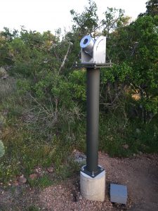
An important requirement for the hardware installation is a mounting location that is very sturdy. If the Cyclope is mounted on a building or other location that is subject to movement from wind or vibration, then you will be measuring that movement instead of the seeing. I decided to make a metal pier and attach the pier to a concrete footing. I did this for several reasons. The metal pier provides a heavy and sturdy mount, the pier is adjustable in azimuth to aid in polar alignment, and the pier is relatively tall at 5.0 feet (152.4 cm) to get the Cyclope further away from ground level temperatures. Care was also taken in constructing the pier and footing to make sure the mounting bolts were aligned to true north to minimize the final azimuth and latitude adjustments after installation of the Cyclope on the pier (Image 3).
The Cyclope Seeing Monitor has three waterproof DIN connectors. The three connections provide power and serial line, an Ethernet connection and a final connection for a temperature and humidity sensor. The serial line provides data communication for the temperature and humidity sensors, as well as control for the heated front window. The Ethernet line connects the camera for control and image acquisition. The external temperature and humidity sensors are installed on a bracket that is mounted on the side of the camera.
The Cyclope system comes with a full suite of software, including video drivers, image capture software and the Cyclope control software. Using the software, I configured the camera with a fixed IP address and installed the Ethernet camera video drivers and the control software. Software installation was easy and painless. Once the software was connected to the camera, I waited for night fall to make the final polar alignment and initialization.
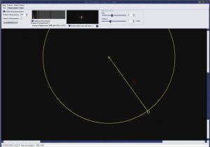
The Cyclope control software has a nice user interface to aid in fine tuning the polar alignment. Upon start-up, the control software starts the camera and shows a current video image with an adjustment overlay. The overlay is a circle with true north at the center. The circle around true north indicates the path of Polaris. The overlay also has a target reticle along the circumference of the circle and this is where Polaris should be centered (Image 4).
When I started up the camera for the first time, I could see the image of Polaris near the target reticle, which required an adjustment of the azimuth and latitude of the Cyclope camera on the pier until Polaris was centered in the reticle. Once done, I tightened up all the bolts on the pier and mount. This only has to be done once. The Cyclope manual has detailed instructions on how to make this fine polar alignment.
Once polar alignment is complete, there are a few other software settings that should be made, including your longitude and latitude, the gain of the camera and exposure interval and ftp upload server and password. Also, the number of tip-tilt measurements to be obtained prior to computing a valid seeing measurement can be set. If the camera is running at 50 frames per second, setting the number of tip-tilt measurements to 3000 will yield a computed seeing value every minute.
The manual gives suggestions and advice for these settings. I found the manual to be informative and sufficient for both the hardware and software installation
Features
The Cyclope Seeing Monitor housing weighs 9.5 kilograms (20.9 pounds) and is very solidly constructed using high-grade, colorless anodized aluminum components and stainless-steel socket-head cap screws. The system is watertight and has watertight connectors, and is designed to operate continuously outdoors.
The control software has numerous features to aid in polar alignment and camera set up. Once the camera is polar aligned, measurements begin automatically each night. The Cyclope software has a main screen where the video exposure and gain can be adjusted, along with a current video showing the target star measurements and histogram.
The Cyclope software automatically begins seeing measurements when the sun is below the horizon and when the stars are visible. The system allows the user to set the number of degrees the Sun must be below the horizon for seeing measurements to begin automatically. In addition, the user can set the maximum seeing threshold and
measurements above which amount will be discarded.
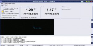
The control software includes a status screen indicating the last measurement in arc seconds at the local Polaris position and the zenith, as well as a current video screen showing the live, rapid-fire measurements of the target star. Each zenith seeing measurement is stored in a data file that can be examined later and imported to a spreadsheet for further analysis (Image 5).
In addition, the status screen gives a computation of R0 or the Fried parameter, named after David L. Fried. The Fried parameter is a coherence length – or a diameter. For telescope apertures smaller than R0, the imaging resolution is determined primarily by the diffraction limit of the telescope. In other words, the seeing won’t interfere with the telescope achieving a resolution approaching its diffraction limit. Of course, with a telescope that has an aperture greater than the R0 parameter, atmospheric turbulence will prevent the telescope from achieving its diffraction limit.
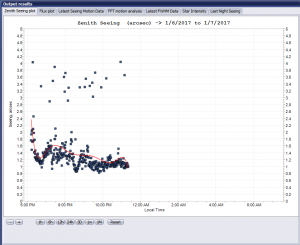
The control software also includes a plot window that provides graphs showing the current night’s seeing over time, the prior night’s seeing over time, the last 3,000 tip-tilt measurements for the current seeing computation and star lux level. The star lux level is helpful to indicate clouds, if the lux level drops too low. Each of these graphs can be adjusted with respect to the time frame over which measurements are plotted. In addition, the ftp feature of the control software will upload these graphs to a web site for public display (Image 6).
The system has four temperature sensors and two humidity sensors to monitor internal and external temperature and humidity and to control heating of the camera window to prevent dew from forming. Control of camera window heating is user defined based on temperature and humidity thresholds that are relevant to the location of the camera. Once these thresholds are set, the system will monitor outside/inside temperature and humidity levels and control the camera window heating system automatically. The temperature and humidity readings are stored in a data file and the control software provides a graphing interface showing this information over time. Using the control software’s ftp upload feature, the temperature and humidity graphs can be uploaded to a web site for public display.
Operation and Monitoring Results
I have been running the Cyclope Seeing Monitor for some time now and am quite pleased with its operation and the insight it provides about my local seeing conditions. Alcor Systems has been helpful in answering any questions I’ve had about set up and configuring the camera options.
My Cyclope seeing measurements closely correlate with predictions from my clear-sky chart and from plate solves with my telescope and camera, however, there are some nights when the Cyclope system indicates the seeing is appreciably better than what the clear-sky chart predicts. This is good news, so I don’t miss out on an imaging opportunity.
At my location, the seeing fluctuates depending on the season. For example, during the spring, the seeing is variable, but in the summer, it improves becoming very stable. This is due to high pressure systems sitting over Texas pushing the jet stream north. Seeing during the summer is excellent and sometimes drops below 1.0 are second. The average seeing during the summer is between 1.2 and 2.5 arc seconds.
With the Cyclope Seeing Monitor system, it is also interesting to watch the seeing change during the night. Some nights, the seeing will vary periodically in an up-and-down cycle, indicating waves of turbulent air that come and go every two or three hours. This insight is useful when examining individual sub frames later – it helps me understand whether there was an equipment or focus problem or simply deterioration in the seeing. I also like having last night’s seeing graph to compare to the current night.
Now that I can “see” the seeing, I watch it carefully, and it’s the first thing I do when preparing for a night of imaging. I always have great expectations when night falls to get those first few seeing measurements. If you want to see for yourself, you can view my seeing monitor web page with live updates every night.
 Ken Kattner is a business attorney by day and an astrophotographer by night. Ken serves as a member of the board of directors and as treasurer for the International Dark Sky Association. From his Putman Mountain Observatory located in the Texas Hill Country, Ken has learned that preserving the beauty of our night skies is a significant natural resource important to each of us. That insight has led Ken to help a number of Hill Country cities design and implement lighting codes to promote more efficient, dark-sky-friendly outdoor lighting. Ken continues to work with cities, businesses, individuals, and advocacy organizations to preserve the dark skies in the Texas Hill Country.
And to make it easier for you to get the most extensive telescope and amateur astronomy related news, articles and reviews that are only available in the magazine pages of Astronomy Technology Today, we are offering a 1 year subscription for only $6! Or, for an even better deal, we are offering 2 years for only $9. Click here to get these deals which only will be available for a very limited time. You can also check out a free sample issue here.