
A DYI Telescope Joystick Project
[Tinkering: To study or improve something through the trial-and-error process of taking it apart or building it from scratch. Just as the journey is often more enjoyable than the destination, the process of tinkering is often even more fun than the result achieved.]
Whether professional or amateur, we astronomers love our equipment. Over the last four decades we’ve seen the digital revolution drive advances in optics, mounts, imaging, and image processing. However, there is a downside to these innovations. Today’s equipment is rather unfriendly to tinkering and do-it-yourself projects. It takes a substantial level of expertise and boldness to customize an expensive scope, mount, or camera.
Craft telescopes used to be common. Today, the rare craft scope can still be appreciated for its beauty, but it cannot compete functionally without integrated electronics and software control systems. On the other hand, digital technology is also the basis for image processing, and this field is rich with tinkering and do-it-yourself attitude. Beautiful pictures of craft scopes have been replaced with beautiful images of the heavens.
What makes image processing inviting to tinkering and self-expression? I believe because it has a shallow learning curve. The process consists of small, manageable steps. Experiments are cheap in terms of dollars and invested time. You can achieve powerful results, but at no point in the process are you likely to feel stuck, frustrated, or at risk of irreversible mistakes. If anything, you are overwhelmed by the number of alternatives that you would like to explore.
On the other hand, tinkering with a modern scope, mount, or camera has a steep learning curve. There may be only a few, or a single path forward. One must do sufficient research to minimize the risk of damage to the equipment, and one can no longer learn how the equipment works by simply taking it apart. Too much basic functionality is buried within the electronics and software.
Digital Hardware Tinkering Made Easy
Over the last several years, a movement has grown to bring do-it-yourself attitude back to hardware design, built around inexpensive micro-controllers (Arduino) and single-board computers (Raspberry Pi and Beaglebone). These boards and their supporting environments are specifically designed for tinkering and a shallow learning curve. I decided to try an Arduino-based project for myself and, hopefully, to build something useful for my scope.
Telescope Joystick Design Objectives
At the top of my astronomy wish-list was a telescope joystick for motion control. Sometimes I just want to take my scope for a drive across the moon or through the Milky Way. I enjoy discovering and studying objects for myself, then going to my sky-map application to see how well I did. However, I find the four-button (NSEW) motion-control system cumbersome. Frankly, it sucks the fun out of driving the scope. If my car had push buttons for controlling speed and direction, I wouldn’t want to drive it either.
My design objectives for a telescope joystick motion controller: (1) The scope moves in graceful arcs and accelerates/decelerates smoothly. (2) One handed, eyes-free operation (my eyes stay on the eyepiece). (3)The joystick extent and direction map to slew speed and direction. (4) “Forward” on the joystick maps to “Up” in my view. (5) A circular motion on the joystick (constant r, constant rotational velocity) yields a circular motion in my view, albeit out of phase.
My mount takes the LX200 command set, through an RS232 port. I verified that the command set supports a separate slew rate for each axis and that the slew rate variable is continuous, with at least three digits of resolution. In theory, this is sufficient to support my design goals.
What’s “Up”?
The key requirement for an intuitive telescope joystick is a proper definition of “up.” First, note that the direction of “up” does not need to be perfect, only close. After all, when using your computer mouse, you don’t move it in perfect alignment with your computer screen.
When the mouse’s direction of motion is close to expected, your hand-eye coordination will take over. On the other hand, turn your mouse by 90 degrees and a lifetime of hand-eye coordination will be working against you. You have to consciously think about a simple rotation before every move. But the fix is simple. The mouse needs to be properly rotated to align with the “up” of your screen.
The same is true with the NSEW buttons of a telescope. No doubt you have tried rotating a scope’s keypad to align the buttons with the corresponding motion. Unfortunately, the rotated keypad no longer fits in one hand.
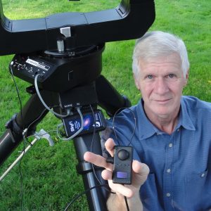
Imagine the NSEW buttons on your keypad replaced with a joystick that can be rotated. I consider this the most intuitive interface. Unfortunately, an analog stick that can also be rotated does not currently exist, for any price. In my hand box (Image 1), I used a joystick and a separate rotary encoder, mounted on the left side. The encoder “rotates” the joystick coordinate system. My layout is designed for right-handed usage.
Controlling “Up”
In general, every time you reposition the scope or your body, you will introduce a rotation error. The procedure to compensate consists of pushing up on the telescope joystick. Imagine I see Mars moving in the 4 o’clock direction. Then with my thumb and first finger, I rotate the encoder such that 4 o’clock is shifted to the 12 o’clock position. The rotation doesn’t need to be perfect. Anywhere between 11 and 1 o’clock is fine – your hand/eye coordination will take over. Hence, one doesn’t need a high-precision encoder. Mine encodes 96 counts per rotation and cost about five dollars.
The angle of rotation depends of several things, but partly it depends on how you position your head with respect to the scope. Unless you intend to attach directional sensors to your head and your diagonal, then the angle of rotation cannot be calculated and an empirically determined rotation is required. Once you accept the idea of an empirically determined rotation, the rest of the algorithm for graceful motion control is straightforward (see Sidebar).
The compute power of the Arduino is far more than needed. One can read the joystick and compute new slew rates in about 4 milliseconds; even faster if you wanted to write clever (and perhaps unreadable) code. This corresponds to 250 slew updates per second. But RS232 at modest baud rates cannot handle this amount of traffic. Nor do we know how much time the scope requires to process each command. I desire the scope to move gracefully and, by experimentation, chose ten updates per second. The update rate is controlled by intentionally inserting a delay in the calculation.
Shortcuts
In addition to the telescope joystick control, I also added a few programmable “shortcut” buttons to my hand box. Note the four small buttons located immediately below the stick. The first button turns the OTA fan on/off. The second button controls the built-in dew heater and cycles through four states: 0, 30, 70, and 100 percent. The third button selects the “slew-mode,” as described below. The fourth button is currently unused.
For my equipment, I’ve defined three slew modes. The more equipment you have, the more slew modes you may desire.
The first is astronomical mode for viewing through my 90-degree diagonal. This is where the rotary encoder is required to align forward on the stick with “up” in the field of view. This left-handed mode sets a minimum/maximum slew speed of 0.003 to 0.15 degrees per second and uses encoder angle.
The second is terrestrial mode for viewing with my 45-degree diagonal. It too sets slew speed at from 0.003 to 0.15 degrees per second, but does not use encoder angle. When terrestrial images are rotated, I find the viewing uncomfortable and rotating the joystick doesn’t help solve this problem. Hence, I always position the diagonal to provide a non-inverted, non-rotated image. For this mode, the rotary encoder value is not necessary and is ignored.
The third slew mode is 1X-finder mode. In it, “up” is well defined as the zenith. For my altitude/azimuth mount, this is a fixed rotation angle of zero. Again, the rotary encoder and its current value are ignored. For an equatorial mount, “up” is still the zenith, but there is a nonzero rotation angle. One could use the rotary encoder to empirically set the “up” direction. Or one could query the scope’s time and position, then calculate the proper angle to the zenith.
The display is an organic LED which works well in cold weather and is completely black in the off state. When a short-cut button is pushed, the display lights up for three seconds and reminds me of the button’s function and new state.
Project Hardware and Configuration
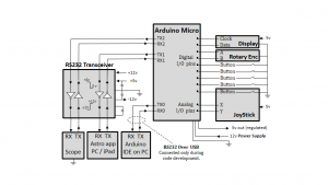
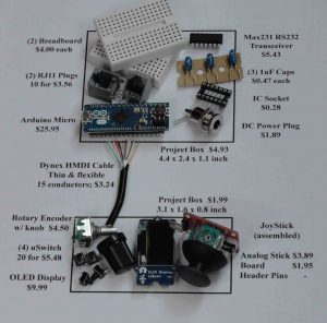
The hardware used in this telescope joystick project is shown in Image 2. This hardware and my hand box layout are personal choices. There are many alternatives that could work as well, or better. But the picture gives one a feel for the modular controls and their cost. Support for the Arduino includes many modules, including motor drivers, sensors, WiFi, Ethernet, etc. Also shown is my wiring schematic (Image 3). The electrical “engineering” for this project consists of nothing more than connecting the proper lines of communication between modules.
A significant portion of this project was managing communication over RS232. I chose to connect my joystick directly to the scope and to issue LX200 commands, but an alternative would be to connect at the PC and issue ASCOM commands. Either way, one needs to get comfortable with building hardware that either issues or consumes commands over RS232.
This is a tall mountain to climb, but the shallow learning curve of the Arduino makes the hike enjoyable. I started with simple queries to the scope – time, date, etc. Next, I snooped on the commands and responses between my sky-map application and scope. Third, I got my shortcut buttons and the joystick working. And finally, I added the logic to manage the RS232 traffic between all four entities – scope, Arduino, sky-map app, and the Arduino IDE (integrated development environment on your PC).
Success?
I judge this project’s success in two ways. First, is the telescope joystick as simple to use and as intuitive as a computer mouse? Yes, for both viewing through the eyepiece and the 1X finder. I did find that it is best to set the minimum slew speed lower than required. This gives your vision system quick feedback on direction before the object has moved too far.
My second test for project success is whether the Arduino lives up to its reputation of powerful, yet easy and fun to use. I found the entire design process intuitive and welcoming to trial and error. The programming language is C, but there is no need for fast or compact code. A beginner’s “Learn-C” manual will suffice.
For tools, I required a voltmeter and a USB oscilloscope to check for signals between RS232 ports. For RS232 data rates, the cheapest USB oscilloscope will suffice. This project was almost entirely fun, I learned a great deal about my scope, and I was almost never stuck or frustrated. What more could one hope for in their hobby? I’d recommend the Arduino (or equivalents) for similar projects.
Design Notes – Pseudo-code for graceful telescope joystick motion control.
- Read stick’s x/y values:
x = analogRead( stick_x )
y = analogRead( stick_y )
- Offset and scale x & y so the stick’s rest position is 0.0 and the N,S,E,W extremes of travel correspond to values of ±1.0.
- If left handed coordinate system, x = -x
- Convert to polar coordinates:
r = sqrt( x2 + y2)
theta = arctan2 ( y, x )
- RadiusStop = ~0.01 = small circle that defines the stick’s rest position.
If r<RadiusStop, then command the scope to stop slew (resumes tracking) and exit loop.
- If rotating coord system:
theta = theta – RotaryEncoderAngle
- Calculate slewSpeed, increasing exponentially with r:
slewSpeed(r) = slewMin * (slewMax/slewMin) r
– For example, if slew Min and Max are 0.1 to 0.4 degrees/second:
slewSpeed (0.00) = 0.1 However, r<0.01 so no motion.
slewSpeed (0.01) = 0.101 Threshold for first motion.
slewSpeed (0.50) = 0.2
slewSpeed (1.00) = 0.4
- Convert to scope’s coordinate system.
Same expressions for equatorial mounts, except replace Alt with Dec, and Az with RA.
slewAlt = slewSpeed*sin(theta) slewAz = slewSpeed*cos(theta)
- If scope is aligned and its altitude angle can be trusted:
slewAz = slewAz/ cos(scope altitude)
Without this, a circle on the stick maps to an ellipse in the field of view.
- Limit the maximum speed of slewAz:
abs(slewAz) ≤ MaxSupportedScopeSlew
- Create command string.
It takes four LX200 commands to modify the scope’s motion. The first two specify the slew rates (elevation and azimuth). The last two command the scope to move. If the scope is already in motion, the scope accelerates or decelerates to the new slew rates. Your scope may vary! commandString “:RE0.133:RA0.034#:Mn#:Me#”
- Forward commands to scope:
SerialScope.print( commandString )
- Delay as necessary to decrease the frequency of slew updates.
- Loop.
 By John Stirniman
John Stirniman has degrees in Semiconductor Device Physics (BSEE) and Business (MBA). He lives in Vancouver, WA, and is recently retired after 38 years manufacturing and designing semiconductors. Astronomy has always been his favorite of many hobbies. His first book purchased in the second grade was “Know the Stars” by Lester del Rey. He still owns the book and uses its charts and his hand drawn constellations as his primary star atlas. He is currently relearning tensor calculus, relativity, and cosmology, so he can decide for himself the fate of the universe.
###
 And to make it easier for you to get the most extensive telescope and amateur astronomy related news, articles and reviews that are only available in the magazine pages of Astronomy Technology Today, we are offering a 1 year subscription for only $6! Or, for an even better deal, we are offering 2 years for only $9. Click here to get these deals which only will be available for a very limited time. You can also check out a free sample issue here.